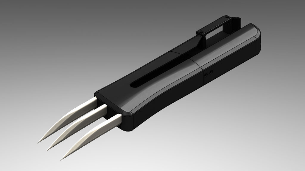
*SNIKT*
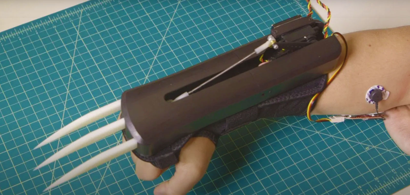
This tutorial will teach you to build bionic claws using our MYOWARE® 2.0 Muscle Sensor. Simply flex your forearm muscle and *SNIKT*, a fraction of a second later the 4 inch claws extend out. Relax your forearm to retract the claws. We’ve even added a muscle-activated locking mechanism in case you want the claws to stay out while keeping your muscle flexed.
Step 1
Print 3D Parts
First off, grab the 3D .STL files from our GitHub repository and either print them at home if you are lucky enough to have a 3D printer or have them printed from a 3D print shop. We use a local print shop, Fineline. Your printed parts might require some sanding and finishing depending on the quality of the print.
Step 2
Connect the Y-Harness
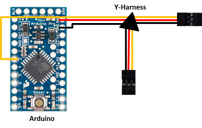
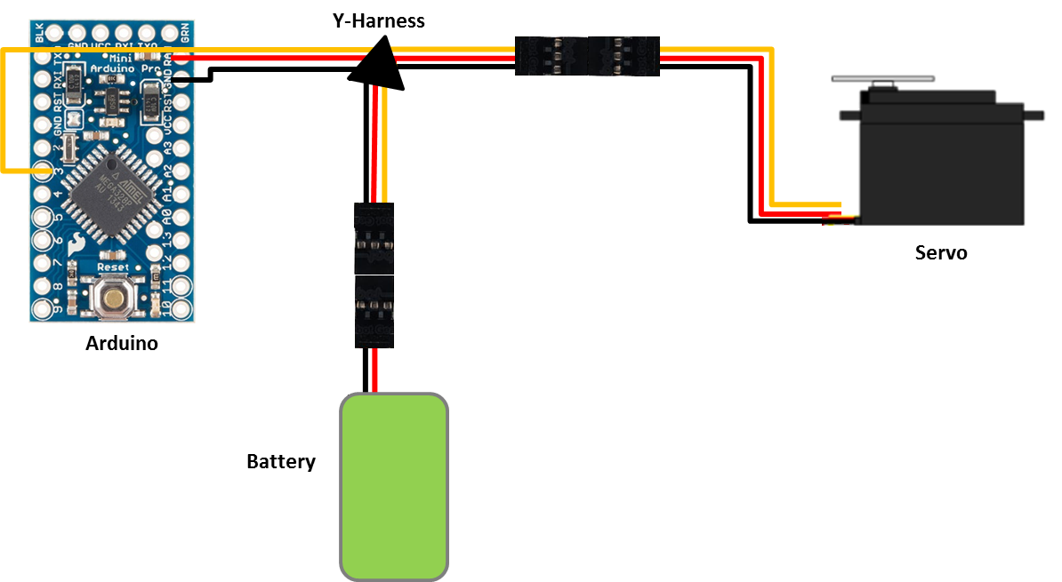
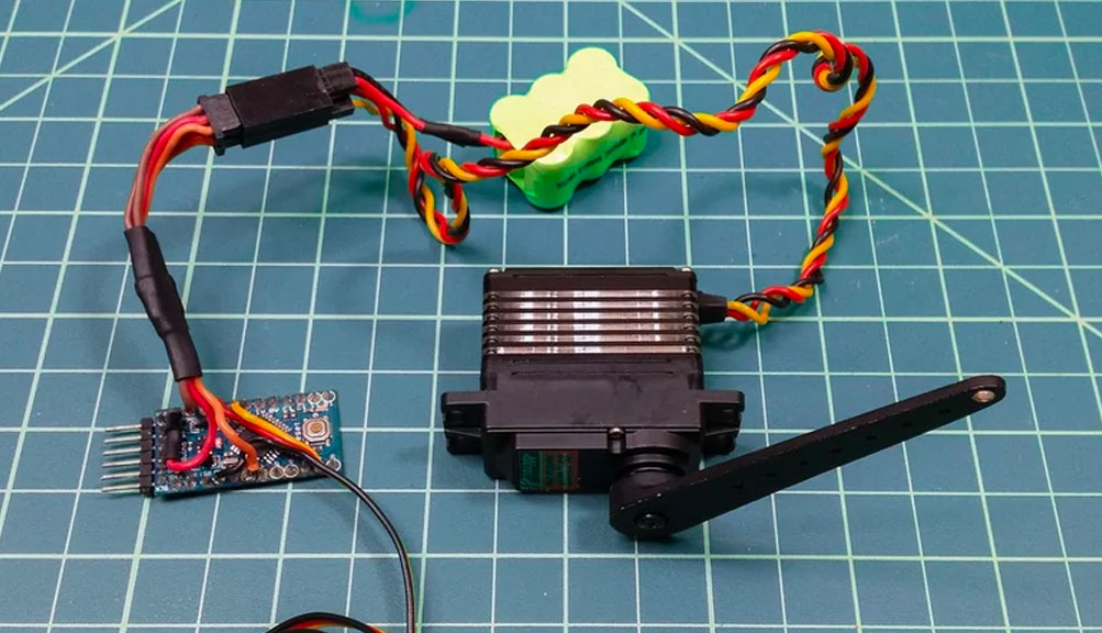
We need to wire the Y-harness to the Arduino board. The Y-harness will allow us to connect both the Arduino and the servo to the 7.2V battery.
- Cut off the female connector of the Y-harness (keep the two socket connector ends – you’ll need them to easily connect the servo and battery) then split and strip the wires.
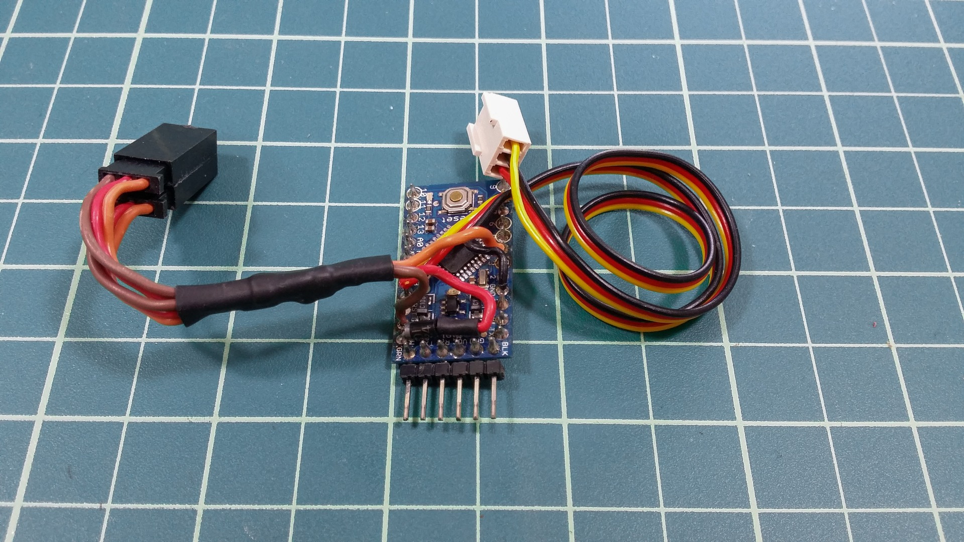
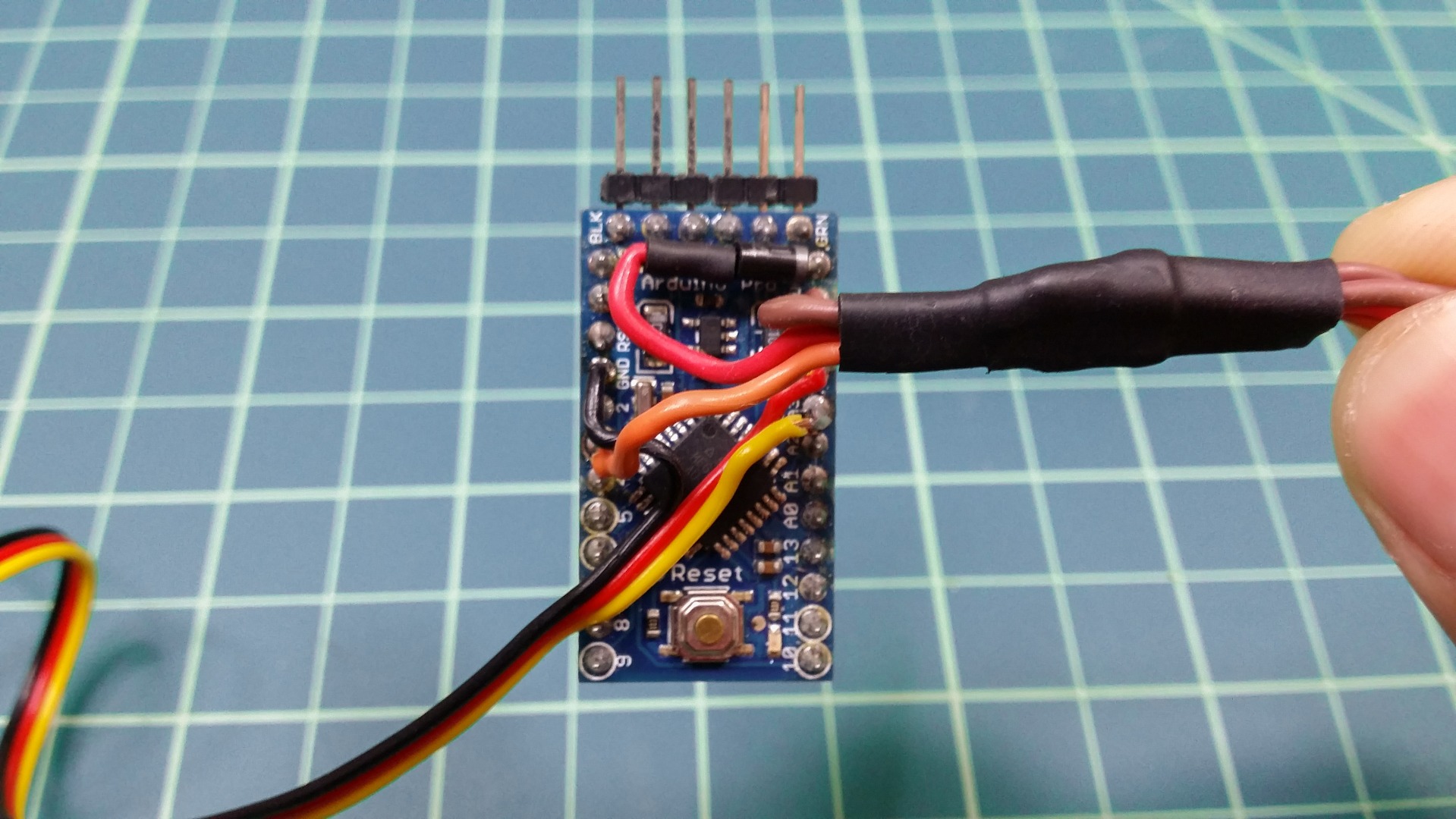
- Solder the red wire to the RAW pin on the Arduino, the black wire to the GND pin on the Arduino, and the yellow wire to the 3rd digital pin.
- Clip off any excess wire
Note: If you find that the Arduino flickers when the servo extends the claws, you’ll need to add a large capacitor between the RAW and GND pins and/or a diode between the y-harness positive wire and the RAW pin. The capacitor is needed if the servo is pulling too much current than the battery can supply. The diode will keep the servo from creating reverse current.
Step 3
Test the Y-harness Wiring
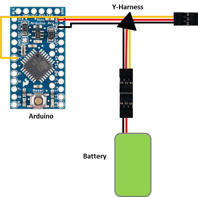
Before we move on you should check to make sure you wired the Y-harness correctly.
- Plug the battery into one of the two sockets of the y-harness.
- The arduino power light should turn on. If it does not, quickly disconnect the battery and recheck your wiring.
- Next, plug the servo into the other socket (disconnect battery first)
- Grab the SweepMod sketch from our GitHub repository and open it in the Arduino IDE.
- In the Arduino IDE, click on Tools and make sure the board is set to “Arduino Pro or Pro Mini (5V, 16 MHz) w/ ATmega328”.
- Upload the sketch to the Arduino.
- If you aren’t familiar with the Arduino Pro Mini, head over to SparkFun and read through their Getting Started tutorial.
- Disconnect the cable and plug the battery back into the remaining socket
- The arduino should turn on and start moving the servo back and forth. If the servo does not move, disconnect the battery and check your wiring.
- Disconnect the battery and servo and you’re ready to move on.
Step 4
Wire the MYOWARE 2.0 Muscle Sensor
Next, we need to connect the muscle sensor.
- Measure the distance from your wrist to your elbow, cut off an equal length of servo wire, and strip both ends.
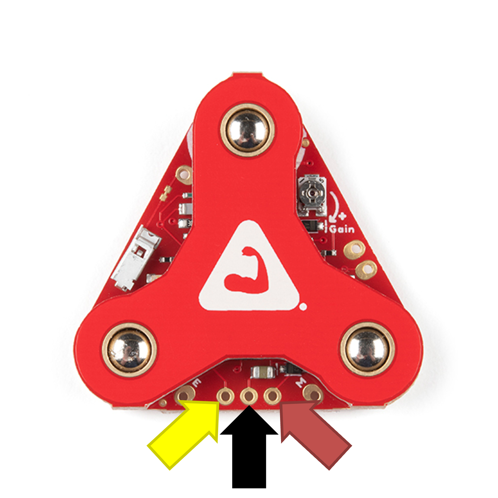
- Insert the yellow wire into the muscle sensor’s output signal pin (ENV), the red wire into the power (Vin) pin, and the black wire into the ground (GND) pin. Note: Unfortunately, the servo wire color order does not match the sensor’s pin order so make sure you’re connecting the wires correctly.
- Solder the wires to the muscle sensor board and clip off any excess wire.
You could alternatively use a 3-pin Molex, JST, or some other type of connector so the sensor can be disconnected from the rest of the setup
Step 5
Connect the MYOWARE 2.0 Muscle Sensor
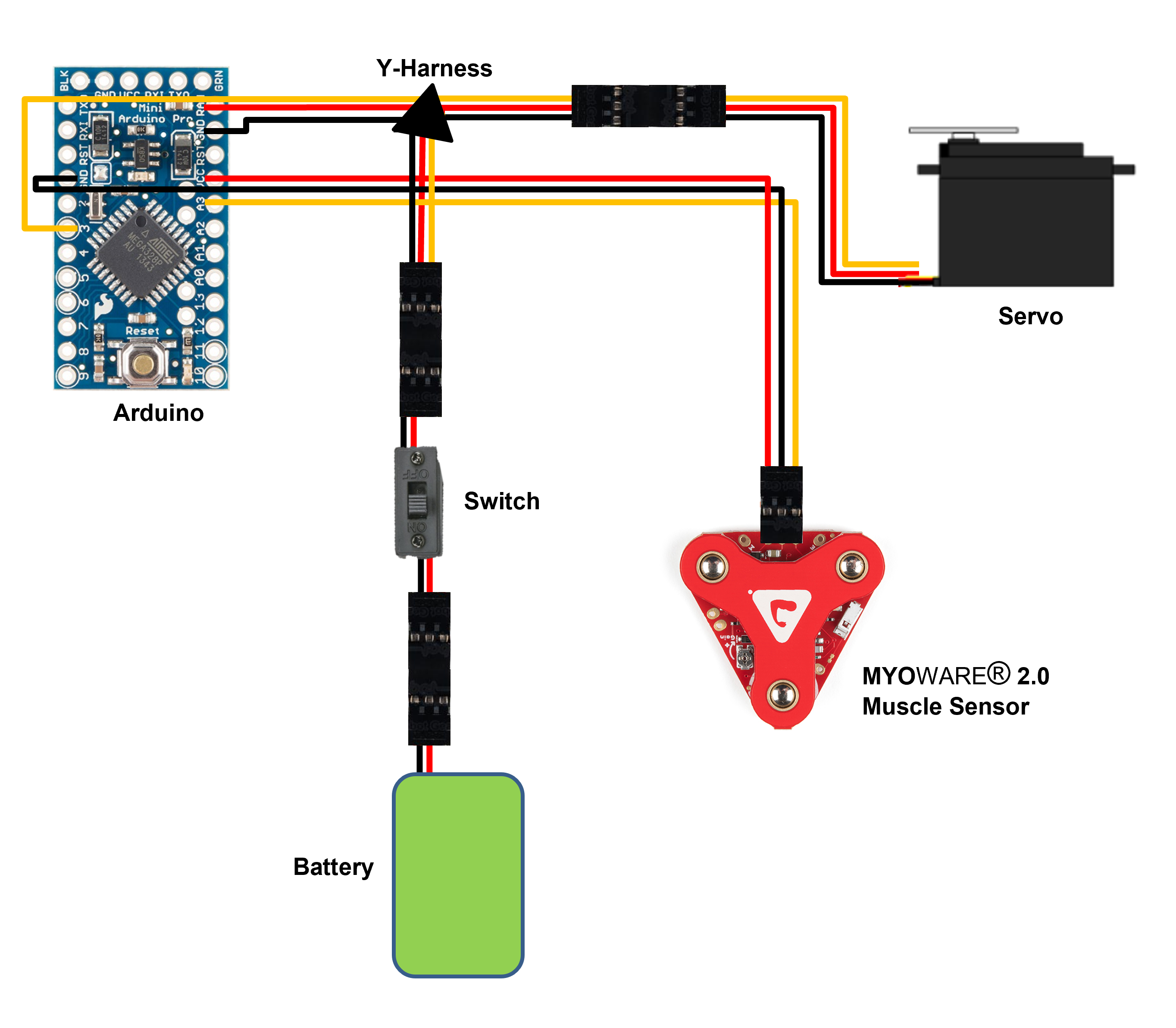
Now we’re going to connect the MYOWARE 2.0 Muscle Sensor to the Arduino board. Since the 7.2V of the battery is too high for the sensor, we’ll use the Arduino’s built in 5V regulator to power the MYOWARE 2.0 Muscle Sensor.
- Split the servo wire that you wired to the MYOWARE 2.0Muscle Sensor and solder the red wire to the Vcc pin, the black wire to the ground pin, and the yellow wire to the 3rd analog pin (A3)
- Clip off any excess wire.
Step 6
Test the MYOWARE 2.0 Muscle Sensor

You’ll want to test the MYOWARE 2.0 Muscle Sensor to be sure it is setup correctly before uploading the new Arduino code
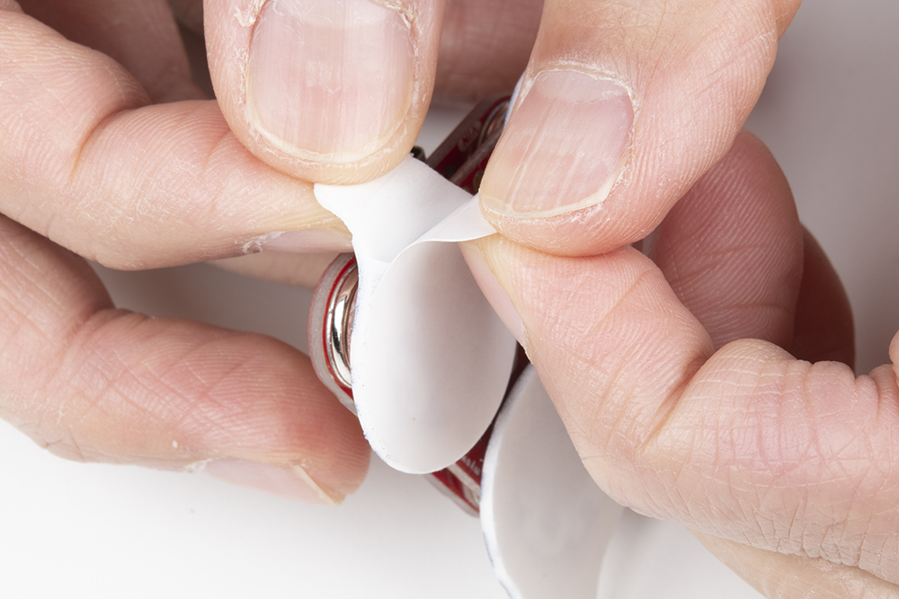
- Use alcohol wipes and gently clean the skin on your forearm.
- Snap three new electrodes onto the MYOWARE 2.0 Muscle Sensor
- Peel off the electrodes and stick the MYOWARE 2.0 Muscle Sensor to your forearm
- Place one of the electrodes that are connected directly to the MYOWARE 2.0 Muscle Sensor board in the middle of your forearm muscle with the other electrode placed along the length of the muscle
- Place the reference electrode nonadjacent to the muscle body that the other electrodes were placed
- Plug in the battery and turn the MYOWARE 2.0 Muscle Sensor on if it isn’t already
- The MYOWARE 2.0 Muscle Sensor’s Vin LED should turn on at this point. If it does not, check your connections and make sure the battery is charged
- The second LED represents the output signal. If this LED does not turn off when your muscle is relaxed, check your connections and electrode placement.
- Next, make sure the MYOWARE 2.0 Muscle Sensor is setup correctly by flexing your forearm muscle
Step 7
Upload the Arduino Sketch

It’s time to upload the Arduino sketch.
- Connect the 5V FTDI programming cable to the Arduino and a computer.
- Grab the Bionic Claws sketch from our GitHub repository and open it in the Arduino IDE.
- In the Arduino IDE, click on Tools and make sure the board is set to “Arduino Pro or Pro Mini (5V, 16 MHz) w/ ATmega328”.
- Upload the sketch to the Arduino.
- Disconnect the FTDI cable.
Step 8
Test the Electronics
Before we start final assembly, let’s make sure the electronics are working as expected.
- Put on the MYOWARE 2.0 Muscle Sensor and turn the system on.
- Try flexing your muscle, the servo should extend when you do and retract when you relax.
If the servo does not move, there are a few things to check:
- Check the battery voltage. You don’t want to waste hours trying to troubleshoot only to realize things aren’t working because your battery is dead.
- Make sure the MYOWARE 2.0 Muscle Sensor’s LED is turning on when you flex (indicating it is working). If not, make sure it’s switch is turned on and the power LED is on.
- Make sure the Arduino power LED is on when you connect the battery. If not, then check the wiring again.
Step 9
Drill and Tap the Enclosure Side Screwholes
With the electronics functional we can move on to assembling the 3D printed parts.
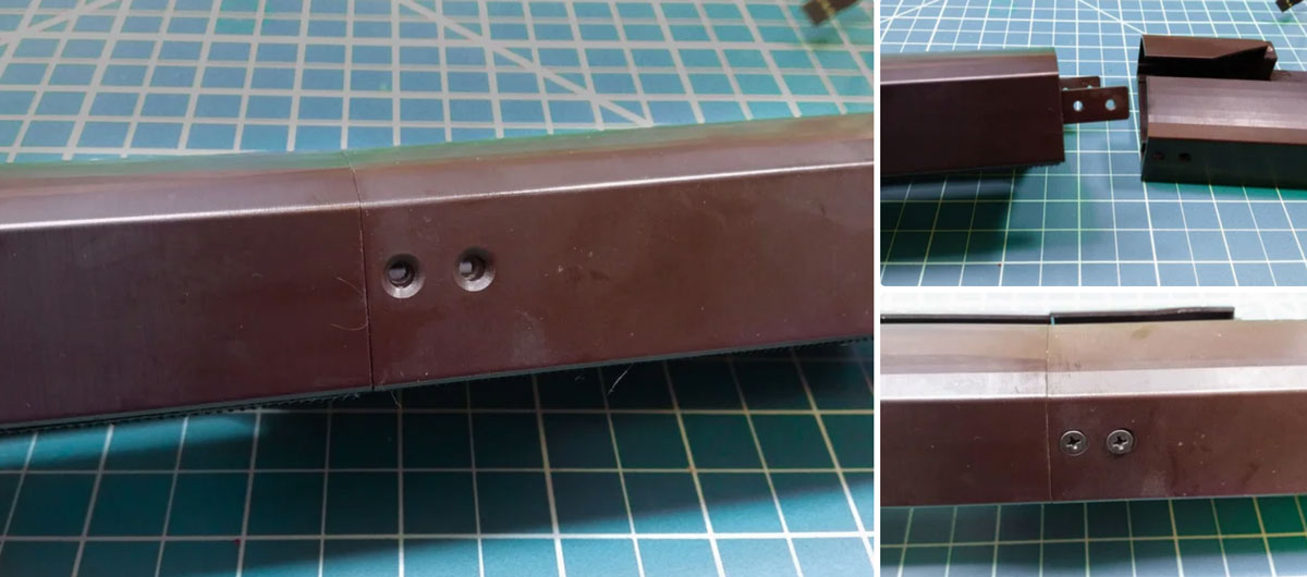
- Take the enclosure back and insert it into the front portion. There are two center punch holes on the tabs of the front section. These should line up pretty closely to the through holes on the back portion.
- Grab your drill and drill bit and drill four holes in the tabs concentric to the four through holes.
- Next, use the tap to create the screw threads in the tab holes. Make sure to keep the tap perpendicular to enclosure side or the screw might not fit flush.
- Grab the 3/16″ screws and test out the new screw holes by screwing them in. Do not over tighten them or you can easily strip the plastic screw threads on the tab.
- Remove the screws before proceeding.
Step 10
Prep the Servo Mount
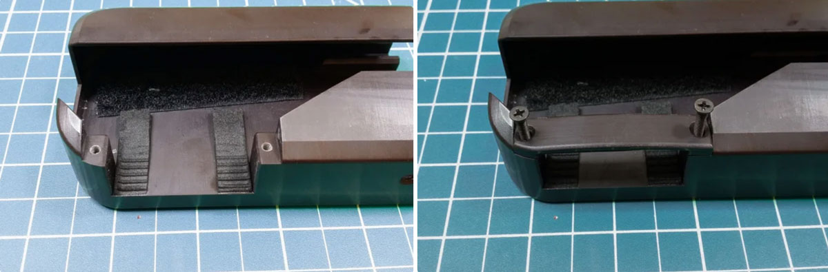
The servo will be mounted in the rear portion of the back enclosure part. There are two holes already present but they need to be tapped for the screws.
- Carefully use the tap to carve out the screw threads in these holes.
- Place the servo bar on top of the holes and screw in the 3/4″ screws to make sure the threads are in working order.
- Cut off a couple 1/2″ long strips of the sticky-backed foam and adhere them to the bottom of the back enclosure between these two screw holes. This will keep the servo from sliding on the smooth plastic when a torque is applied. Note: you can do the same for the servo bar.
Step 11
Add Velcro to the Enclosure
We’re going to need a way to adhere the enclosure pieces to the wrist brace sleeve but we want to make it temporary so we can remove the enclosure if something breaks or needs tweaked.
Take the wide sticky-backed velco strips and adhere the hooks side to the underside of both the back and front enclosure pieces. You’ll need to trim along the curves to make sure you get the velcro to cover the front piece completely.
Step 12
Prep the Servo Horn
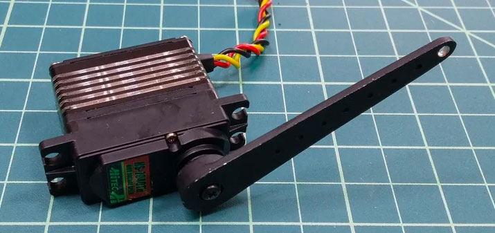
The 2″ servo horn unfortunately comes with holes too small for the servo linkage but it’s easily fixed. Simply grab your drill and drill out the hole closest to the servo horn tip. Attach the servo horn to the servo and install the servo linkage to the hole you just drilled.
Step 13
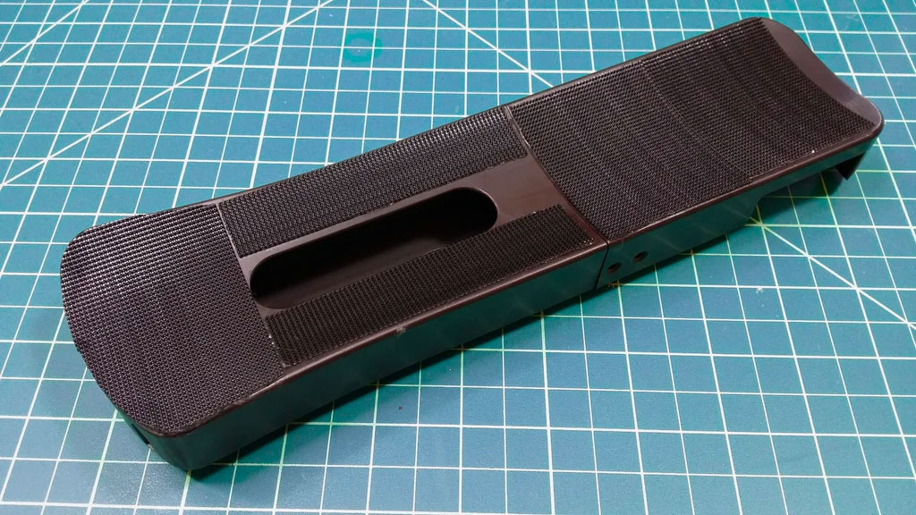
Prep the Claws
The claws don’t need much prep. You should try sliding the claws along the track to make sure they run smoothly. If not, use some very fine sandpaper and smooth out any parts that catch or bite into the tracks.
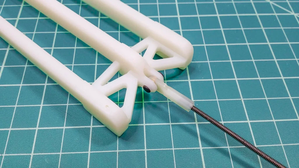
Then grab the two 3D printed tabs and a servo linkage. Hold the servo linkage in the bracket at the back of the claws and insert a tab into each side of the bracket. You might want to dab a drop of super glue on them to keep them from falling out.
Step 14
Assemble the Servo Linkage
Now we’re getting somewhere – time to start putting the pieces together!
- Insert the claws into the tracks of the front enclosure.
- Attach the front and back enclosure pieces together and screw them in place.
Note: Don’t screw them in all the way or they will interfere with the claws running up and down the track. You can move the claws until they are in front of the holes, screw in the screws until you feel them contact the claws and back the screws out just enough to give some clearance. - Insert the servo into the servo mount and secure it with the brace and screws. The servo should be positioned with the arm closest to the rear of the enclosure and pretty close to the centerline.
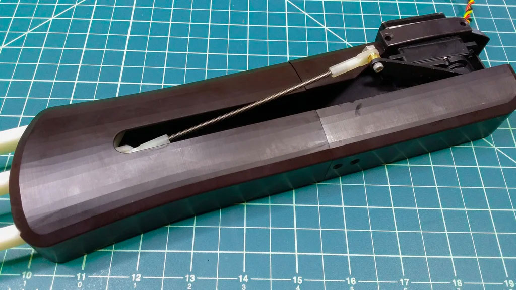
- Move the servo arm to the fully extended position (You can do this by turning on the electronics, flex your muscle to extend the servo, then turn the system off while it is in this position) and move the claws so that they are fully extended as well.
- Measure the straight-line distance between the two servo linkages with some extra to take into consideration that you’ll need some extra length to thread the rod into the linkages (should be around 4″)
- Cut off a piece of threaded rod with this length and carefully screw it into the linkage on the claws.
- Next detach the linkage from the servo (using the thumb screw) and screw it on to the other end of the threaded rod.
- Move the servo arm through extension and retraction a couple times to make sure the claws move appropriately.
- Afterwards, to prepare for inserting the electronics in the next step, detach the linkage from the servo arm and remove the servo from the mount
Step 15
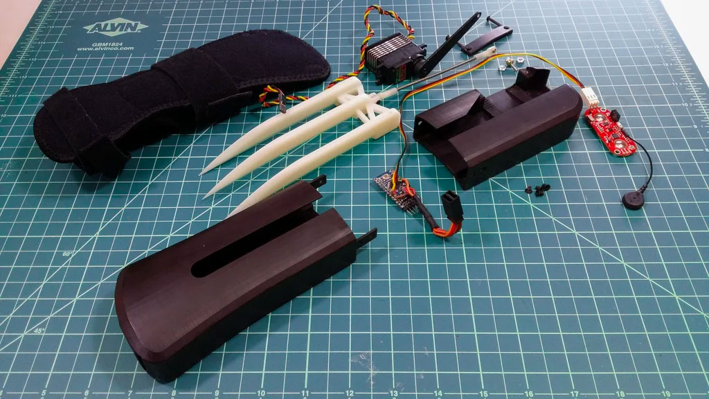
Insert the Electronics
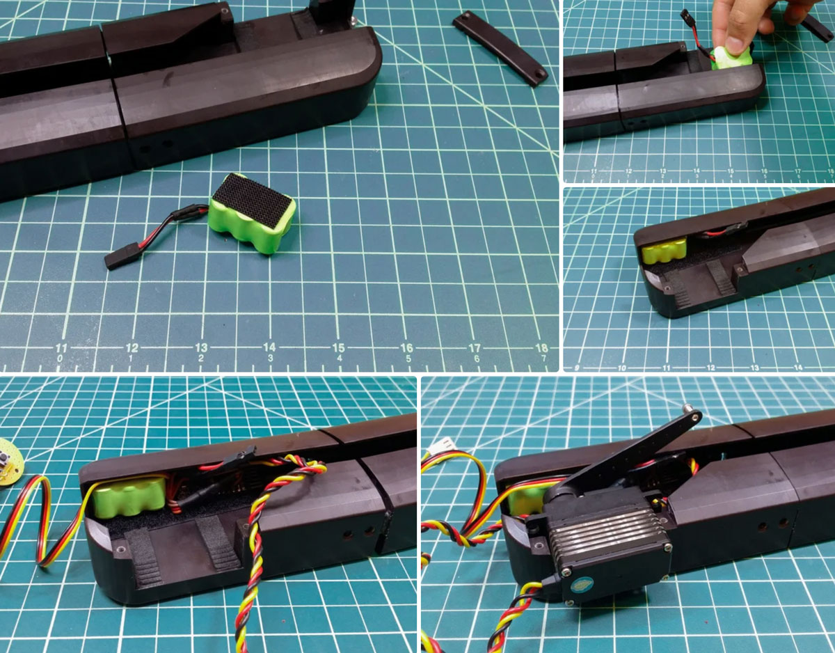
Now we’ll need to squeeze all the electronics into the side pocket of the back enclosure opposite to the servo mount.
- Cut off a reasonable square of sticky-backed Velcro and stick it onto the bottom of the battery and the other side in the back corner of the enclosure pocket.
- Slide the Arduino into the pocket just in front of the battery with the MYOWARE 2.0 Muscle Sensor wire running out the slot at the back end of the enclosure. and under the servo arm. The servo wire should be threaded through this slot as well. You could Velcro the arduino board in place but it’s really not that necessary and stays reasonably in place on its own.
- Remount the servo and reassemble the servo linkage.
- If not already, plug in the servo wire into one of the y-harness sockets. Do not plug the battery in until you’re ready to use the completed system.
Tips
- Take out some of the length of the servo wire and y-harness to keep things less cluttered.
- Super glue the two y-harness sockets together to make connecting the battery and servo wire easier once everything is in place.
- Remember the electronics don’t have a switch built in so whenever you connect the battery, the system will turn on. We’ve added a delay so you can do this without the servo pinching your fingers on accident but it might be a good idea to add a switch between the battery and the y-harness.
- If you want to get fancy, you can run the MYOWARE 2.0 Muscle Sensor’s wire behind the battery so it doesn’t interact with the servo arm at all.
Step 16
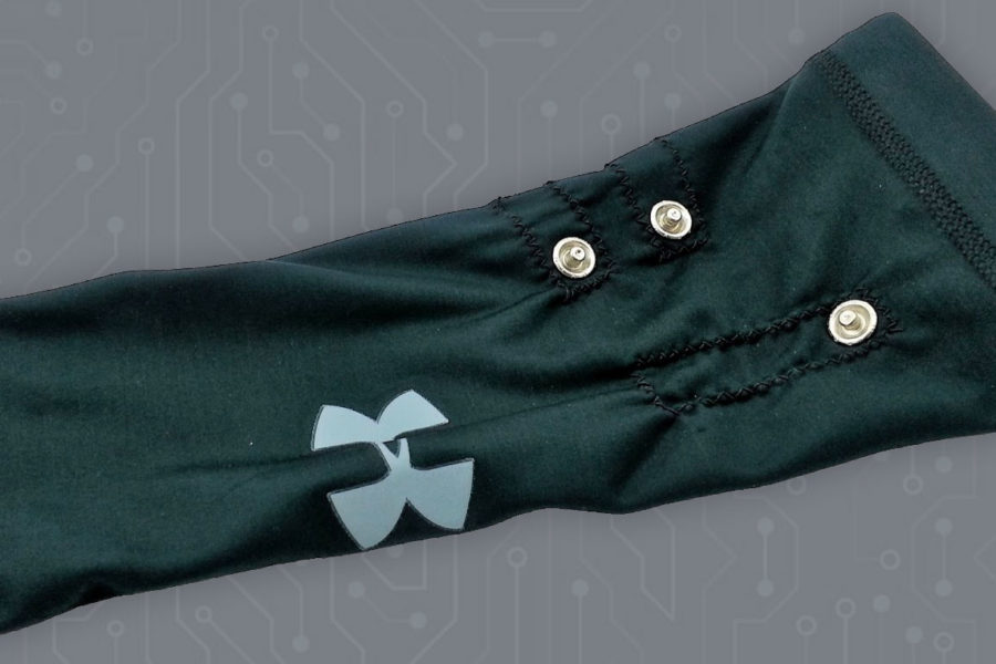
Attach the Enclosure to the Wrist Sleeve
Last part of the assembly is to attach the enclosure to the wrist sleeve.
- Remove the plastic wrist brace from the cloth sleeve.
- Place the enclosure on the sleeve. Note: you might have to remove and reattach a few times to get the positioning and alignment just right.
Although not necessary, we added some Velcro straps to securely fix the enclosure to the arm. Try it without first and then if you feel the enclosure wobble around or just doesn’t feel secure, add the straps.
Step 17
Time to Play!
That was the last step! Your Bionic Claw system should be fully operational.
- Flex to extend the claws
- Relax to retract them.
- If you flex for two seconds straight, you’ll trigger the lock mechanism and the claws will stay extended when you relax afterwards.
- To take the lock off, simply flex for another two seconds and the claws will retract when the unlock is triggered.
Now get started on the other hand!