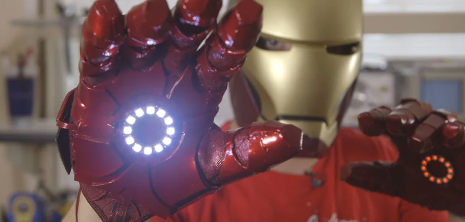
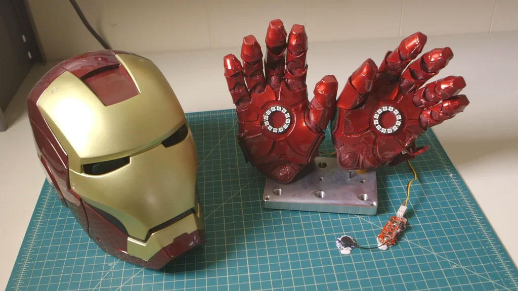
I AM IRON MAN!
For this project, we’ll teach you to build an Iron Man inspired repulsor glove using our MYOWARE 2.0 Muscle Sensor. Simply flex your forearm muscle and hear the repulsor charge up, then relax your forearm to fire (lighting up the LEDs on your palm and playing explosion sound effects). As an added flair for realism, when you turn on the system, JARVIS’s voice takes you through the boot up and calibration sequence.
Step 1
Rewire the Speaker
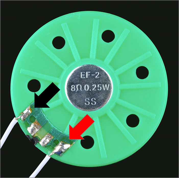
These thin speakers come with flimsy and fragile wires already soldered to them so we’ll want to first remove these and solder more robust wiring.
- Take out your soldering iron and remove the existing wires from the back of the speaker
- Cut off a couple inches of the servo wire, rip off and throw away the yellow wire, and strip ~1/8 inch from each end of the red and black wires.
- Split one side of the red/black wire just enough to reach both solder tabs on the back of the speaker
- Solder the red wire to the speaker’s positive (+) solder tab and black wire to the negative (-) solder tab
Step 2
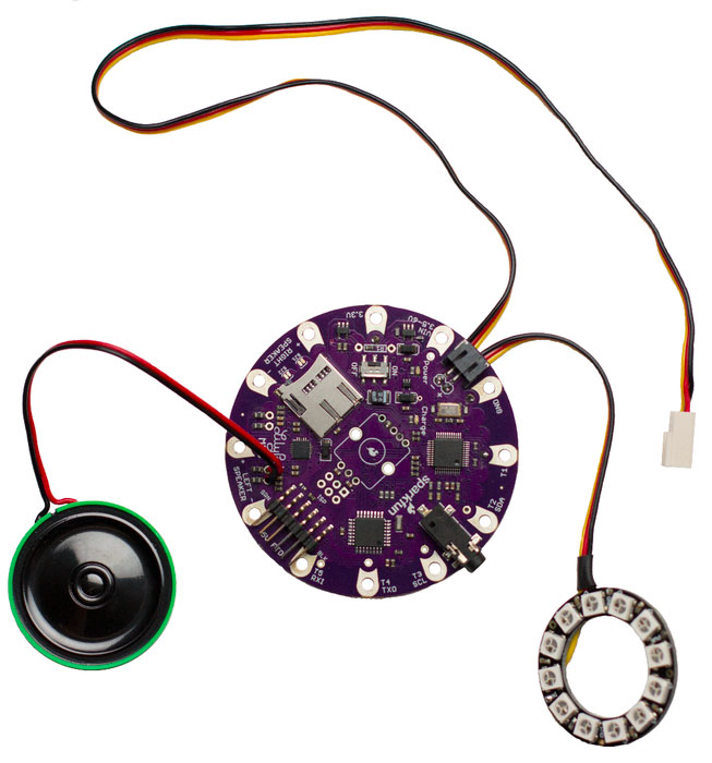
Connect the Speaker to the Lilypad MP3
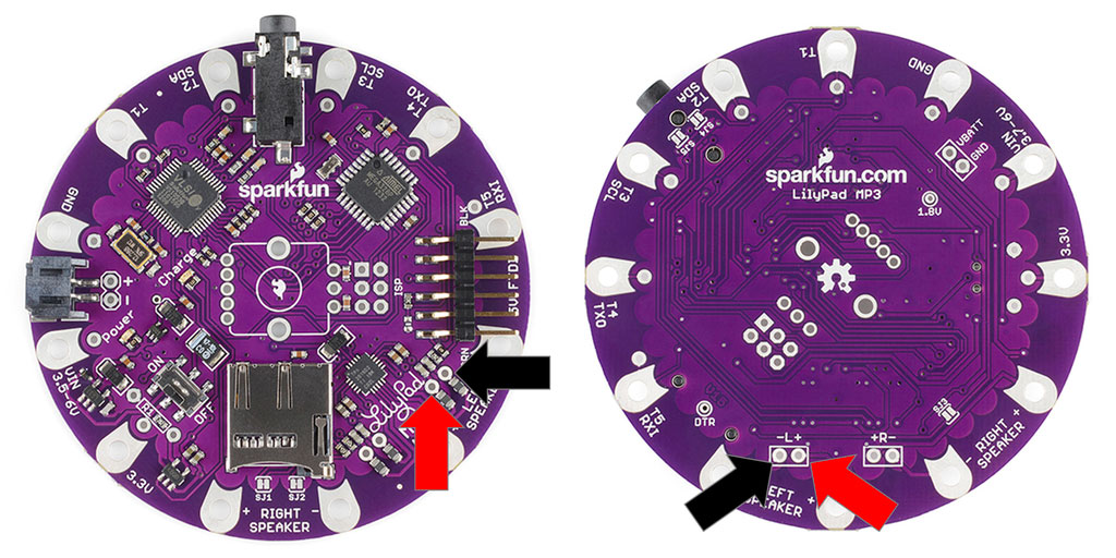
Next, we’ll solder the speaker wire to the Lillypad MP3.
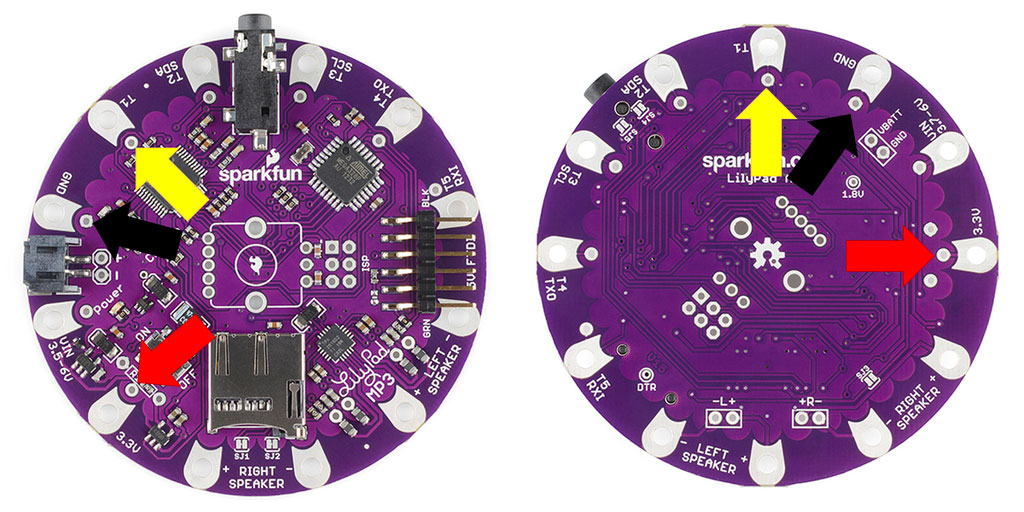
- From the topside of the board, insert the red/black wires into the Lilypad’s left speaker pins (see picture).
- The red wire should go in the positive (+) pin and the black wire in the negative (-) pin.
- Solder the wires to the board and clip off any excess wire.
You could alternatively use a 2-pin Molex, JST, or some other type of connector so the speaker can be disconnected from the rest of the setup.
Step 3
Test the Lilypad MP3
Now that the speaker is connected. We should check to make sure this standard Lilypad MP3 setup is working properly before start hijacking pins for the NeoPixel and uploading new code.
The Lilypad MP3 comes with the Trigger sketch preloaded. This sketch will play a sound from the microSD disc when the associated trigger pin (T1, T2, T3, T4, and T5) are pulled to ground.
- Copy the sound files from our GitHub repository to the microSD disc.
- Insert the microSD disc into the Lilypad disc slot.
- Plug the LiPo batter into the JST battery port on the Lilypad
- Turn the Lilypad MP3 switch to ON.
- Using spare wire or alligator clips, connect/hold one end to the Lillypad’s GND pin and tap any of the trigger pins. You should hear a different sound clip for each trigger pin.
- If you don’t hear any sound, double check that the positive pin on the speaker is attached to the positive left speaker pin on the Lilypad. Same with the negative pin.
- If you still don’t hear any sound, you might want to contact Sparkfun to help troubleshoot the Lilypad MP3.
Step 4
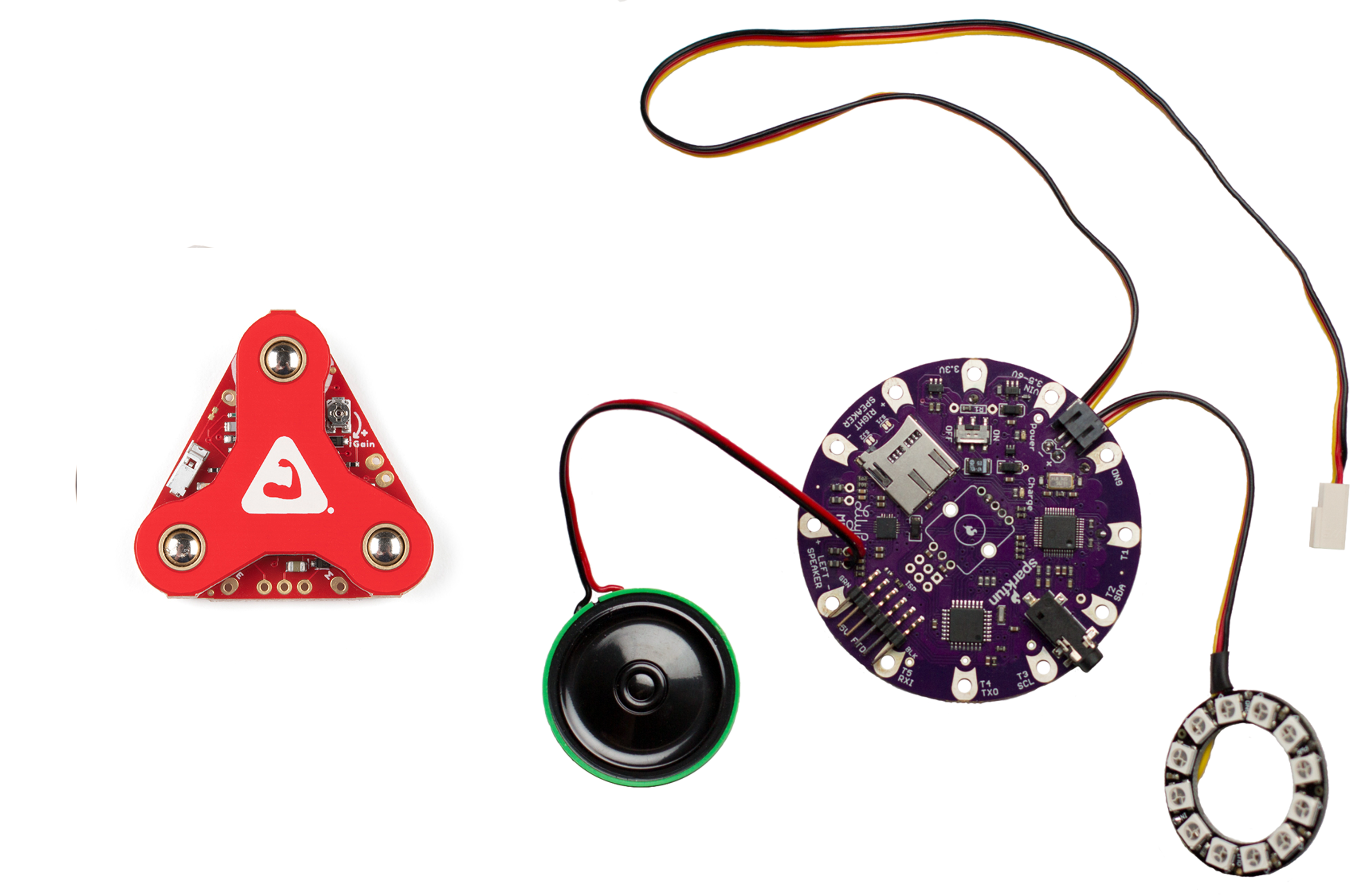
Wire the NeoPixel Ring
OK by this point, the Lilypad MP3 should be able to play sound through the speaker you’ve attached. Now, we’re going to work on hooking up the NeoPixel ring to make an awesome glove repulsor.
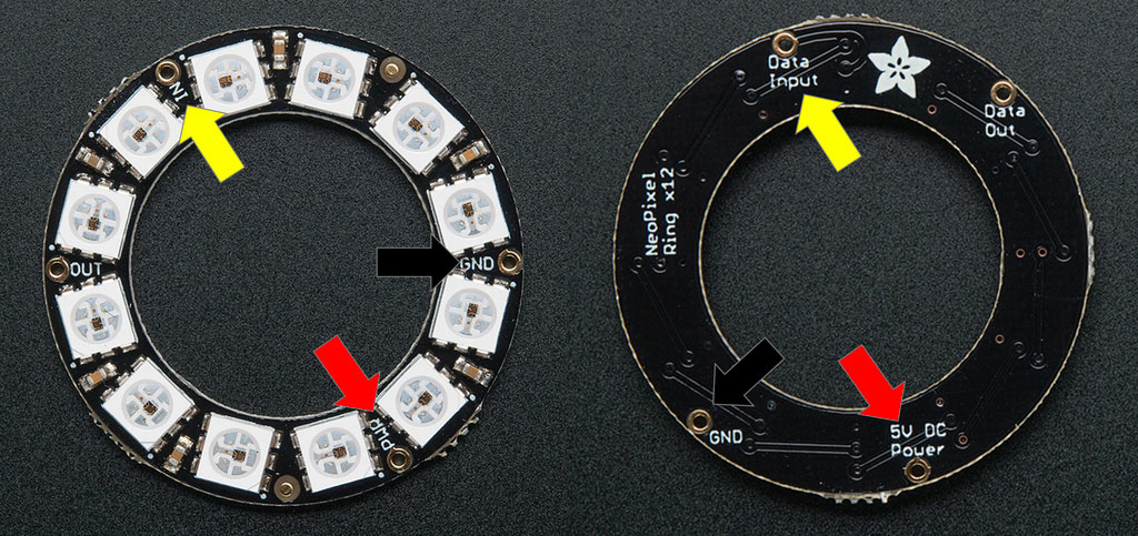
- Cut off a reasonable length of servo wire (or three strips of wire if you’re not using servo wire) and strip ~1/8 inch from both ends.
- From the bottom side of the board, insert the servo wire into the NeoPixels pins.
- The red wire should go in the power (PWR / 5V DC Power) pin, the black wire in the ground (GND) pin, and the yellow wire in the input signal (IN / Data Input) pin.
You could alternatively use a 3-pin Molex, JST, or some other type of connector so the NeoPixel can be disconnected from the rest of the setup.
Step 5
Connect the NeoPixel Ring to the Lilypad MP3
Next, we’ll solder the NeoPixel wire to the Lillypad MP3.
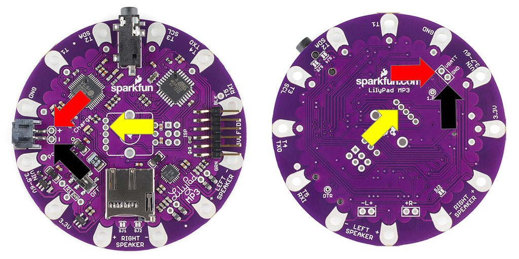
- From the bottom side of the board, insert the NeoPixel wires into the Lilypad’s pin shown in the picture. The red wire should go in the positive (+) pin next to the JST battery port (labeled VBATT from below), the black wire in the negative (-) pin, next to the JST port (labeled GND from below), and the yellow wire in the ROT-LEDB pin (yellow arrow in the picture).
- Solder the wires to the board and clip off any excess wire.
Notes:
- The ROT-LEDB pin connects to the D5 pin of the microcontroller.
- The VBATT pin is unfortunately not switched which means the NeoPixel is always on when the battery is connected; you’ll need to disconnect the battery when you turn off the Lilypad MP3 to avoid draining the battery. Or add a switch between the battery and the JST port. Or use a connector to wire the NeoPixel to the LilyPad and disconnect it when not in use.
- You may have noticed the Lillypad uses a 3.3V based microcontroller and the NeoPixel is designed for 5V and are scratching your heads a bit on how this setup works. This setup (as recommended by Adafruit) works because the 3.7V of the battery powers the NeoPixel while the control signal is 3.3V and this difference is not too great for the NeoPixel’s drivers to overcome. This is why the NeoPixel isn’t connected to the 3.3V pin of the Lilypad.
Step 6
Test the NeoPixel Ring
Time to test the NeoPixel ring. To do this, we’ll need to upload new test code to the Lilypad MP3’s microcontroller.
- Connect the 5V FTDI programming cable to the Lilypad and a computer.
- Grab the Arduino NeoPixel test sketch from our GitHub repository and open it in the Arduino IDE.
- In the Arduino IDE, click on Tools and make sure the board is set to “Arduino Pro or Pro Mini (3.3V, 8 MHz) w/ ATmega328”.
- Yup, that’s right; you need a 5V FTDI but use the 3.3V board setting… it’s a bit unusual.
- Upload the sketch to the Lilypad MP3.
Note: Make sure the Lilypad MP3’s power switch is set to ON. You’ll get a sync error otherwise. - Disconnect the FTDI cable, connect the LiPo battery, and turn the Lilypad on. The NeoPixel should turn on and loop through two light sequences.
- The first is a “rainbow comet” where the light travels around the ring in a clockwise fashion changing colors as it goes,
- The second will “wipe” along the ring coloring each LED green and then pulse in brightness a few times before “wiping” the LEDs off.
- These are the same sequences that occur when turning on the completed glove.
Step 7
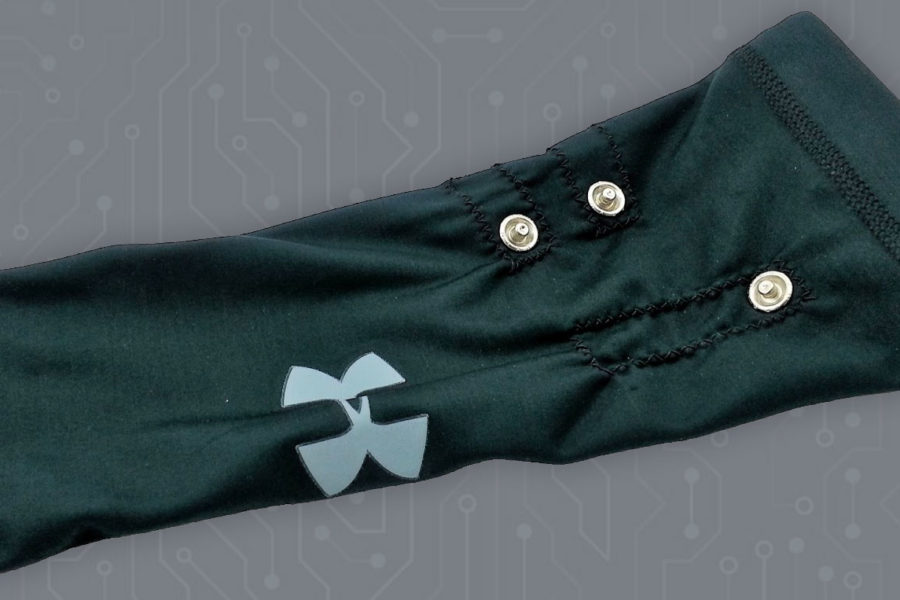
Wire the MYOWARE 2.0 Muscle Sensor
Almost done! All we have left is to connect up the muscle sensor and upload the final Arduino sketch.
- Measure the distance from your wrist to your elbow, cut off an equal length of servo wire, and strip both ends.
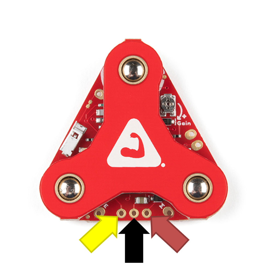
- Insert the yellow wire into the muscle sensor’s envelope output pin (ENV), the red wire into the power (Vin) pin, and the black wire into the ground (GND) pin.
- Note: Unfortunately, the servo wire color order does not match the sensor’s pin order so make sure you’re connecting the wires correctly.
- Solder the wires to the muscle sensor board and clip off any excess wire.
You could alternatively use a 3-pin Molex, JST, or some other type of connector so the sensor can be disconnected from the rest of the setup.
Step 8
Connect the MYOWARE 2.0 Muscle Sensor
Next, we’ll solder the MyoWare wire to the Lillypad MP3.
- From the bottom side of the board, insert the servo wire into the Lilypad’s pins (see picture). The red wire should go in the 3.3V pin, the black wire in the ground (GND) pin, and the yellow wire in the first trigger pin (T1).
- Solder the wires to the board and clip off any excess wire.
Step 9
Test the MYOWARE 2.0 Muscle Sensor
You’ll want to test the MYOWARE 2.0 Muscle Sensor to be sure it is setup correctly before uploading the new Arduino code.
- Snap three new electrodes onto the MYOWARE 2.0 Muscle Sensor.
- Peel off the the electrodes and stick the MYOWARE 2.0 Muscle Sensor to your forearm.
- Place one of the electrodes that are connected directly to the MYOWARE 2.0 Muscle Sensor board in the middle of your forearm muscle with the other electrode placed along the length of the muscle. (See Advanced Guide for more information)
- Place the reference electrode nonadjacent to the muscle body that the other electrodes were placed.
- Plug the LiPo battery into the LilyPad and turn the LilyPad on.
- The MYOWARE 2.0 Muscle Sensor power LED should turn on at this point. If it does not, check your connections and make sure the LiPo is charged.
- The second LED represents the output signal. If this LED does not turn off when your muscle is relaxed, check your connections and electrode placement.
- Next, make sure the MYOWARE 2.0 Muscle Sensor is setup correctly by flexing your forearm muscle.
- The second LED on the sensor board should light up when you flex your muscle and turn off when you relax. If it does not, check your connections and electrode placement.
Step 10
Upload the Arduino Sketch

You’re so close!
By now…
- the speaker has been tested and plays the sound clips from the Lilypad,
- the NeoPixel has been tested and the Lilypad is able to turn
- the MyoWare sensor has been tested and it’s on-board LED lights up when flexing
It’s time to upload the Arduino sketch.
- Connect the 5V FTDI programming cable to the Lilypad and a computer.
- Grab the Arduino IronManRepulsor sketch from our GitHub repository and open it in the Arduino IDE.
- In the Arduino IDE, click on Tools and make sure the board is set to “Arduino Pro or Pro Mini (3.3V, 8 MHz) w/ ATmega328”. Yup, that’s right; you need a 5V FTDI but use the 3.3V board setting… it’s a bit unusual.
- Upload the sketch to the Lilypad MP3.
- Note: Make sure the Lilypad MP3’s power switch is set to ON. You’ll get a sync error otherwise.
- Disconnect the FTDI cable.
Step 11
Test the Completed Hardware
Because you’ve been testing the system step-by-step, all that’s left is to test to make sure the sketch was uploaded correctly.
- Snap on your MYOWARE 2.0 Muscle Sensor, plug in the battery, and turn the bionic system on.
- You should hear the start up SFX as the NeoPixel goes through its start up lighting sequence.
Flex your muscle- You should hear the power up SFX as the NeoPixel glows a dim red.
- Relax your muscle
- You should hear the firing SFX as the NeoPixel intensifies to a bright white.
- After the firing sequence finishes, you should hear the power down sequence as the NeoPixel dims back to red.
Troubleshooting Tips (besides going back and testing phase individually)
- If you feel like you have to flex too hard to get the system to trigger, you have a couple options:
- Increase the MYOWARE 2.0 Muscle Sensor gain – get a screwdriver and turn the gain potentiometer on the sensor clockwise to increase the gain of the sensor. Warning – this could increase false triggering.
- Decrease the system threshold in the Arduino code – the default threshold is just a suggestion you can increase it to make the system require a stronger flex to trigger or decrease to require a weaker flex. Warning – this could increase false triggering.
- Adjust the MYOWARE 2.0 Muscle Sensor placement – improper electrode placement can lead to a smaller signal detected by MYOWARE 2.0 Muscle Sensor
- If you are getting false triggering of the system, you have a couple options:
- Decrease the MYOWARE 2.0 Muscle Sensor gain – get a screwdriver and turn the gain potentiometer on the sensor counter-clockwise
- Increase the system threshold in the Arduino code
- Adjust the MYOWARE 2.0 Muscle Sensor placement – improper electrode placement can lead to muscle cross-talk. Cross-talk is when the signal from an adjacent muscle gets mixed in with the intended muscle’s signal.
Step 12
Attaching the System to the Glove
If you aren’t going to build the foam armor for the glove, the next step is pretty straight-forward.
- Grab either the hot glue gun or the sticky backed velcro and the glove you’ve picked out.
- Attach the Lilypad and the speaker to the back side of the glove.
- Attach the NeoPixel to the middle of the glove’s palm.
Congratulations! You’ve just built your own bionic blaster glove.
Now get started on the glove for the other hand!
Optional
Making the Foam Cosplay Armor
- If you haven’t already, grab the armor files from the GitHub repository.
- Use Pepakura Viewer to open the finger armor files and print them on the cardstock paper.
- Open the palm armor files in Adobe Reader and print them on the cardstock paper as well.
- Cut out the paper pieces with an Exacto knife.
- Put on the glove and hold the finger armor pieces in their intended place to see if they are too big/small
- If they are not sized properly, you’ll need to adjust the scale in Pepakura.
- Click on 2D Menu, go to Change Scale, and select either Scale Factor, Increase Scale 10%, or Decrease Scale 10%. Scale Factor will allow you to change the scale in increments other than 10%
- You might need to repeat this step a few times before you get the scale correct. The armor in this tutorial was increased by 10% and then trimmed one at a time to get the fit to feel correct.
- Once satisfied with the scale, use the cardstock pieces and a sharpie pen to trace their outline on the foam sheets. Make sure to label the foam pieces accordingly.
- To make the opposite hand, simply flip the pieces over.
- Cut out the foam pieces with the Exacto knife.
- Cut 45 degree V-shaped grooves along the fold lines to get crisp bend lines.
- Glue the pieces together with the hot glue.
- For the palm armor, attach the knuckle piece to the lower palm piece first making sure to place the pieces that boarder the repulsor such that they form as close to perfect circle as you can. Take your time and make sure to get this part right. These are the most important pieces since the repulsor is the focal point of the armor and it will really stand out if the pieces boarding the circular repulsor aren’t quite right.
- Only glue the top palm upper piece at the end opposite of the Velcro section. This was used to embed the speaker into the top of the glove.
- Figure out how you want to position the Lilypad MP3 between the glove and foam armor upper palm. Cut a slot in the upper palm bottom section to allow the speaker to be slid through.
- Position the speaker between the top and bottom upper palm pieces and cut out a circle in the top piece smaller then the diameter of the speaker.
- If you used a connector to attach the NeoPixel to the Lilypad, cut a hole in the lower palm and thread the wire through such that the NeoPixel can be Velcroed/Glued to the foam armor but the wire can be threaded between the foam armor and the glove to the Lilypad on the upper palm.
- Gently whisk hot air over all the pieces’ surfaces with the heat gun to seal the EPA foam.
- Don’t heat the foam too much or it will melt. Quickly waving the gun back and forth over the foam should be enough.
- As the foam seals, you should be able to see the foam turn slightly shinier. Makes it easy to tell were the hot air has passed over already.
- Apply a couple coats of plastic adhesion promoter on all the pieces. Follow instructions on the can.
- Apply a couple coats of the primer. Follow instructions on the can.
- Apply a couple coats of the toreador red paint. Follow instructions on the can.
- Apply a couple light coats of a clear coat to protect the paint.
- Hot glue the painted pieces to the base glove.
- Velcro the Lilypad MP3 to the back of the glove and fit the battery where ever there is room.
- Hot glue the NeoPixel to the palm.